

🖲️ 传感器#
机器人需要传感器来观察周围的世界。 在 Genesis 中,传感器从场景中提取信息,利用场景状态计算数值,但不会影响场景本身。
传感器可以使用 scene.add_sensor(sensor_options) 创建,并使用 sensor.read() 或 sensor.read_ground_truth() 读取。
scene = ...

# 1. 向场景添加传感器
sensor = scene.add_sensor(
    gs.sensors.Contact(
        ...,
        draw_debug=True, # 在场景查看器中可视化传感器数据
    )
)

# 2. 构建场景
scene.build()

for _ in range(1000):
    scene.step()

    # 3. 从传感器读取数据
    measured_data = sensor.read()
    ground_truth_data = sensor.read_ground_truth()
当前支持的传感器:
IMU(加速度计和陀螺仪)Contact(每个刚体连杆的布尔值)ContactForce(每个刚体连杆的 xyz 方向上的力)KinematicContactProbe(基于穿透的触觉探针)ElastomerDisplacement(软体触觉位移场)Proximity(到被追踪网格表面的距离)TemperatureGrid(刚体连杆上的体素化温度场)RaycasterLidarDepthCamera
传感器的示例用法可以在 examples/sensors/ 下找到。
IMU 示例#
在本教程中,我们将介绍如何在机械臂的末端执行器上设置惯性测量单元(IMU)传感器。IMU 将在机器人沿圆形路径运动时测量线性加速度和角速度,我们将使用真实的噪声参数实时可视化数据。
完整的示例脚本可在 examples/sensors/imu_franka.py 获取。
场景设置#
首先,让我们创建仿真场景并加载机械臂:
import genesis as gs
import numpy as np

gs.init(backend=gs.gpu)

########################## create a scene ##########################
scene = gs.Scene(
    viewer_options=gs.options.ViewerOptions(
        camera_pos=(3.5, 0.0, 2.5),
        camera_lookat=(0.0, 0.0, 0.5),
        camera_fov=40,
    ),
    sim_options=gs.options.SimOptions(
        dt=0.01,
    ),
    show_viewer=True,
)

########################## entities ##########################
scene.add_entity(gs.morphs.Plane())
franka = scene.add_entity(
    gs.morphs.MJCF(file="xml/franka_emika_panda/panda.xml"),
)
end_effector = franka.get_link("hand")
motors_dof = (0, 1, 2, 3, 4, 5, 6)
这里我们设置了一个基本场景,包含一个 Franka 机械臂。相机位置使我们能够很好地观察机器人的工作空间,我们确定了末端执行器连杆,IMU 传感器将安装在该位置。
添加 IMU 传感器#
我们通过指定 entity_idx 和 link_idx_local 将 IMU 传感器”连接”到末端执行器上的实体。
imu = scene.add_sensor(
    gs.sensors.IMU(
        entity_idx=franka.idx,
        link_idx_local=end_effector.idx_local,
        pos_offset=(0.0, 0.0, 0.15),
        # 传感器特性
        acc_cross_axis_coupling=(0.0, 0.01, 0.02),
        gyro_cross_axis_coupling=(0.03, 0.04, 0.05),
        acc_noise=(0.01, 0.01, 0.01),
        gyro_noise=(0.01, 0.01, 0.01),
        acc_random_walk=(0.001, 0.001, 0.001),
        gyro_random_walk=(0.001, 0.001, 0.001),
        delay=0.01,
        jitter=0.01,
        interpolate=True,
        draw_debug=True,
    )
)
gs.sensors.IMU 构造函数有以下选项来配置传感器特性:
pos_offset指定传感器相对于连杆坐标系的位置acc_cross_axis_coupling和gyro_cross_axis_coupling仿真传感器错位acc_noise和gyro_noise为测量添加高斯噪声acc_random_walk和gyro_random_walk仿真随时间逐渐产生的传感器漂移delay和jitter引入时序真实感interpolate平滑延迟的测量值draw_debug在查看器中可视化传感器坐标系
运动控制与仿真#
现在让我们构建场景并创建圆形运动以生成有趣的 IMU 读数:
########################## build and control ##########################
scene.build()

franka.set_dofs_kp(np.array([4500, 4500, 3500, 3500, 2000, 2000, 2000, 100, 100]))
franka.set_dofs_kv(np.array([450, 450, 350, 350, 200, 200, 200, 10, 10]))

# 为末端执行器创建要跟随的圆形路径
circle_center = np.array([0.4, 0.0, 0.5])
circle_radius = 0.15
rate = np.deg2rad(2.0)  # 每步的角速度,弧度

def control_franka_circle_path(i):
    pos = circle_center + np.array([np.cos(i * rate), np.sin(i * rate), 0]) * circle_radius
    qpos = franka.inverse_kinematics(
        link=end_effector,
        pos=pos,
        quat=np.array([0, 1, 0, 0]),  # 保持方向固定
    )
    franka.control_dofs_position(qpos[:-2], motors_dof)
    scene.draw_debug_sphere(pos, radius=0.01, color=(1.0, 0.0, 0.0, 0.5))  # 可视化目标

# 运行仿真
for i in range(1000):
    scene.step()
    control_franka_circle_path(i)
机器人在保持固定方向的同时绘制水平圆形轨迹。圆形运动产生 IMU 将检测到的向心加速度,以及基于传感器方向的任何重力效应。
构建场景后,您可以访问测量值和真实 IMU 数据:
# 访问传感器读数
print("Ground truth data:")
print(imu.read_ground_truth())
print("Measured data:")
print(imu.read())
IMU 以命名元组的形式返回数据,字段包括:
lin_acc:线性加速度,单位为 m/s²(3D 向量)ang_vel:角速度,单位为 rad/s(3D 向量)
接触传感器#
接触传感器从刚体求解器检索每个刚体连杆的接触信息。
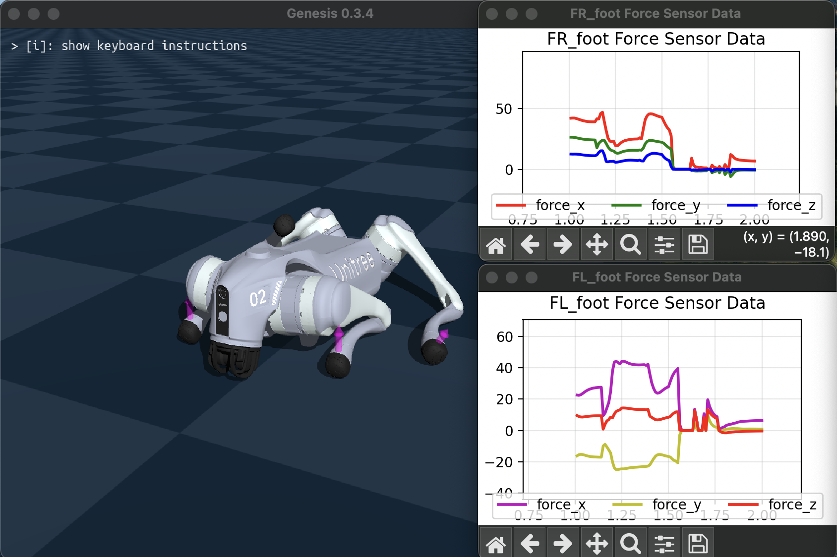
Contact 传感器将返回布尔值,ContactForce 返回相关刚体连杆局部坐标系中的净力向量。
完整的示例脚本可在 examples/sensors/contact_force_go2.py 获取(添加标志 --force 以使用力传感器)。
运动学接触探针传感器 KinematicContactProbe 是一种触觉传感器,它沿着与刚体实体链接关联的”探针”点查询接触深度。与上述从物理求解器获取力的接触传感器不同,此传感器纯粹基于接触穿透深度来估算力:F = 刚度 * 穿透深度 * 探针法线。 带有遥操作控制的示例脚本可在 examples/sensors/kinematic_contact_probe.py 中找到,供您尝试使用。 触觉探针网格可以轻松放置在机器人手或末端执行器上,以模拟触觉传感器的触觉像素(taxels)。
光线投射传感器:激光雷达和深度相机#
Raycaster 传感器通过向场景投射光线并检测与几何体的交点来测量距离。
光线数量和光线方向可以使用 RaycastPattern 指定。
SphericalPattern 支持类似激光雷达的视场和角分辨率规范,GridPattern 从平面投射光线。DepthCamera 传感器提供 read_image() 函数,将光线投射信息格式化为深度图像。有关可用选项的详细信息,请参阅 API 参考。
lidar = scene.add_sensor(
    gs.sensors.Lidar(
        pattern=gs.sensors.Spherical(),
        entity_idx=robot.idx, # 连接到刚体实体
        pos_offset=(0.3, 0.0, 0.1) # 相对于连接实体的偏移
        return_world_frame=True, # 是否以世界坐标系或局部坐标系返回点
    )
)

depth_camera = scene.add_sensor(
    gs.sensors.DepthCamera(
        pattern=gs.sensors.DepthCameraPattern(
            res=(480, 360), # 图像分辨率(宽,高)
            fov_horizontal=90, # 水平视场角度
            fov_vertical=40,
        ),
    )
)

...

lidar.read() # 返回包含点和距离的 NamedTuple
depth_camera.read_image() # 返回形状为(高,宽)的距离张量
演示安装在机器人上的光线投射传感器的示例脚本可在 examples/sensors/lidar_teleop.py 获取。
将标志 --pattern 设置为 spherical 以获得类似激光雷达的模式,grid 获得平面网格模式,depth 获得深度相机。
以下是运行 python examples/sensors/lidar_teleop.py --pattern depth 的效果: